River-Tank Manifold Design

The Concept
Back in 1998, I had a sudden brainwave after trying to work out how better to
house Hillstream Loaches in my aquaria. I wanted to give them a more natural
environment and trying to provide this with a regular tank setup just didn't
work. What they needed for natural conditions was one way flow.....like a river.

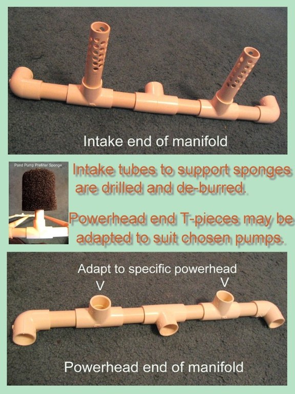
The tubing is three-quarter inch domestic overflow piping, and is assembled
using a special PVC glue. This effectively welds by melting the two joining
pieces, and gives about 30 seconds working time before it won't move again, so
positioning of components is vital. I test fit everything before final glueing
and put reference marks on each part to ensure correct alignment. After 24
hours, this is safe to use once flushed and cleaned in fresh water. A short
length of 1" ID flexible plastic tubing is used as an adapter to better link to
the conical uplift adapter provided by Aquaclear with the Powerheads that I use.
Using various components one can adapt to whatever pump you choose for your
application..
I christened my design The River-Tank Manifold.
Here are all the components laid out after cutting, de-burring and test fitting in the aquarium
Ensure that you test-fit the assembly in your aquarium complete with intake sponges and power-heads before final gluing.
Here is a closeup of each end of the manifold showing the components assembled

Notes

I normally choose power-heads for these species that combined will move the entire capacity of the tank through themselves a minimum of 12 times per hour. As an example two Aquaclear 802s (now called the Aquaclear 70) will turn over a 65USG tank 13.5 times per hour.
Using 3/4" tubing will have its limitations on flowing much above that kind of flow, but is easily hidden under the substrate. To achieve higher flow rates, the size of the power-heads must increase, plus the diameter of the tubing used. International standards differ slightly, but the next increase in size is to around 1.5" diameter. This would obviously increase the flow capacity to a large degree, but be more difficult to disguise in the aquarium.
Many power-heads feature a venturi effect aeration device built in. This normally operates passively by drawing in air via a tube with adjustable intake, that comes with the power-head from the manufacturer. To get the main water-flow down close to the bottom-living fish, I mount the pumps far lower than one does normally if using them on an under-gravel filter uplift.
This will prevent the passive suction operating. Therefore, I find that a positive air feed from a small diaphragm pump is required.
Using this kind of system with Hillstream Loaches, I found a complete change in their behaviour compared to that seen in a conventional aquarium. They are extremely active and entertaining fish in this environment.
Since 1998, many people all over the world have built themselves their own systems to this design or modified it in some way to suit locally obtainable components.
It has been used successfully to breed several species of rheophilic fish other than Hillstream Loaches.
This system is low maintenance, requiring only periodic washing of the intake sponges and cleaning of the pumping chamber of the power-heads to maintain performance.
I find this works best the longer the aquarium is. One of its shortfalls is the pumping device. Power-heads provide a strong, but highly concentrated flow. In short aquaria, the concentrated blast will hit the other end of the aquarium and create more back flow than in a longer tank.
Document Actions


